
 admin
August 11, 2026
admin
August 11, 2026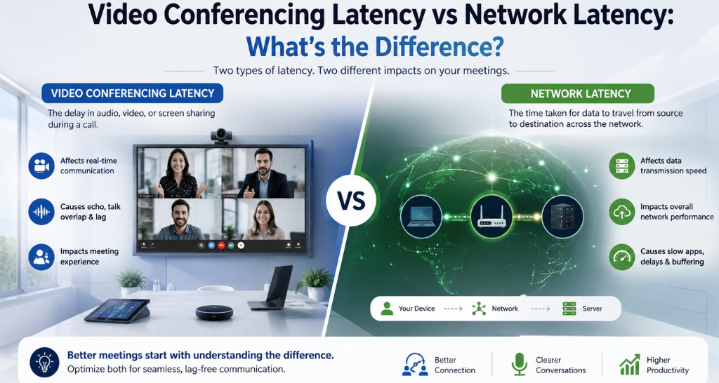
Video Conferencing System: Architecture, Components & Signal Flow Explained
A video conferencing system isn’t simply a camera + microphone + display. Behind every smooth virtual meeting, multiple audio, video, processing, networking, and control technologies work together in real time.
When a participant speaks, the microphone captures the voice and sends it to the audio processing layer, where technologies such as Digital Signal Processing (DSP), Acoustic Echo Cancellation (AEC), Automatic Gain Control (AGC), and noise suppression optimize the signal. At the same time, the camera captures the participant’s image, which is processed before being encoded and compressed for transmission.
The processed audio and video streams then travel across the network to the remote conferencing endpoint or cloud platform. At the receiving end, the signals are decoded, synchronized, rendered, and reproduced through displays and speakers.
In simplified form:
Camera/Microphone → Signal Processing → Encoding & Compression → Network Transmission → Decoding → Display & Audio Reproduction
Any stage can introduce latency, jitter, packet loss, processing delays, or synchronization issues. Therefore, achieving reliable video conferencing requires much more than selecting a 4K camera or high-quality microphone. The complete system must be designed around the room, network, acoustics, user requirements, and interaction between every AV component.
What Is a Video Conferencing System?
A Video Conferencing System is an integrated audio-visual communication environment that enables people in different locations to communicate through real-time video, audio, and content sharing.
The system captures participants through cameras and microphones, processes the signals, compresses them for efficient transmission, transports them through a network, and reproduces the incoming media through displays and speakers. Depending on the application, a professional setup may also include PTZ cameras, beamforming microphones, audio DSPs, codecs, network switches, room controllers, projectors, LED video walls, and centralized management systems.
Unlike a basic laptop-based video call, an enterprise video conferencing system is designed around factors such as room size, seating layout, camera coverage, microphone pickup, acoustic conditions, display visibility, network performance, and integration requirements.
A useful way to understand the system is to divide it into five major layers.
Video Conferencing System = 5 Major Layers
1. Capture Layer
The capture layer converts the physical meeting environment into digital audio and video signals.
It can include:
- PTZ cameras
- Fixed cameras
- Auto-framing cameras
- Speaker-tracking cameras
- Face-tracking systems
The camera selection depends on the room’s dimensions, seating arrangement, viewing angles, required zoom, and participant tracking requirements.
For example, a small huddle room may need only a wide-angle camera, while a large boardroom may require multiple PTZ cameras with speaker tracking.
2. Audio Layer
The audio layer captures and prepares speech for communication.
Typical components include:
- Beamforming microphones
- Ceiling microphones
- Table microphones
- Audio DSP
- Acoustic Echo Cancellation
- Noise suppression
- Automatic Gain Control
- Amplifiers
- Speakers
The objective is not simply to capture sound. The system must deliver clear and intelligible speech while minimizing echo, background noise, reverberation, and unwanted feedback.
3. Processing Layer
The processing layer handles the transformation and management of audio and video signals.
It may include:
- Video codecs
- Video processors
- Audio DSPs
- Control processors
- Video switchers
- Signal converters
This is where captured signals are processed, scaled, mixed, compressed, encoded, and prepared for transmission.
4. Network Layer
The network provides the communication path between the local room and remote participants.
Important network elements include:
- LAN infrastructure
- Managed switches
- PoE
- QoS
- Bandwidth management
- Packet-loss control
- Jitter management
- Latency monitoring
- Firewall and routing infrastructure
Unlike conventional data traffic, real-time audio and video are highly sensitive to network conditions.
5. Presentation Layer
The presentation layer converts processed signals back into something users can see and hear.
It can include:
- Professional displays
- LED video walls
- Projectors
- Confidence displays
- Ceiling or wall-mounted speakers
- Room control interfaces
In larger rooms, separate displays may be used for remote participants and shared content to improve visibility.
How Does a Video Conferencing System Actually Work?
The easiest way to understand a video conferencing system is to follow the audio and video signal flow from capture to reproduction.
Video Signal Flow
Camera → Video Processing → Codec → Network → Cloud/On-Premise Platform → Remote Codec → Display
Audio Signal Flow
Microphone → DSP → AEC/Noise Suppression → Codec → Network → Remote Codec → DSP → Amplifier → Speaker
Although this looks simple, several technical operations occur at each stage.
1. Video Capture
The camera converts the visual scene inside the meeting room into a digital video signal.
Important camera parameters include:
- Resolution
- Frame rate
- Field of View
- Optical zoom
- Digital zoom
- Sensor performance
- Exposure
- Focus
- Low-light performance
For example, a camera capturing at 4K resolution generates considerably more image information than a 1080p camera. However, the final conferencing quality also depends on processing, compression, network conditions, and the display.
2. Video Processing
Before transmission, the captured video may be processed for:
- Scaling
- Cropping
- Framing
- Exposure correction
- Image enhancement
- Camera switching
- Speaker tracking
- Auto-framing
In a multi-camera room, a video processor or control system may determine which camera feed should be sent to the conferencing platform.
3. Encoding and Compression
Raw video contains a huge amount of data and cannot normally be transmitted efficiently without compression.
The encoder compresses the video stream using a suitable codec.
Compression reduces the amount of data that needs to travel through the network while attempting to preserve visual quality.
This creates a balance between:
Image Quality ↔ Compression Efficiency ↔ Bandwidth ↔ Processing Requirements
4. Network Transmission
After encoding, the audio and video streams are transmitted through the network.
Depending on the architecture, the path may involve:
Conference Room → LAN → Firewall/Router → Internet → Cloud Platform → Remote Participant
Enterprise environments may also use dedicated network segments, QoS policies, VLANs, and managed switching infrastructure.
5. Decoding
At the receiving endpoint, the compressed media stream is decoded.
The decoder reconstructs the video and audio information so that it can be processed and reproduced locally.
6. Rendering and Reproduction
The decoded video is sent to the display, while audio is routed through the DSP, amplifier, and speaker system.
The objective is synchronized reproduction so that the participant’s voice and video appear naturally aligned.
If audio and video become noticeably unsynchronized, users may see the participant’s lips move before hearing their voice, creating an unnatural meeting experience.
Video Conferencing System Architecture
Different rooms require different architectures. A small huddle room does not need the same infrastructure as a large boardroom or enterprise command center.
A. USB-Based Room System
A basic architecture may look like:
Laptop → USB Camera → USB Microphone → Conferencing Platform → Display
This approach is relatively simple and is suitable for smaller meeting spaces where the user’s laptop acts as the primary conferencing endpoint.
Best suited for:
- Huddle rooms
- Small meeting rooms
- Flexible workspaces
- Simple BYOD environments
Its main advantage is simplicity, while scalability and centralized control can be more limited.
B. Appliance-Based Room System
A more structured room may use:
Camera + Microphone + DSP + Codec/Room Appliance + Controller + Display
Here, the room has dedicated conferencing hardware rather than relying entirely on a participant’s laptop.
Advantages include:
- Consistent room experience
- Dedicated hardware
- Centralized control
- Better audio processing
- Camera automation
- Easier room operation
This architecture is particularly suitable for professional conference rooms and boardrooms.
C. Integrated AV-over-IP / Enterprise Architecture
Larger deployments can use an IP-based architecture:
Camera → Network → AV Processing → Control → Conferencing Platform → Display
In such environments, audio, video, control, and other AV signals can be distributed across an enterprise network.
This architecture is useful when organizations require:
- Multiple rooms
- Centralized management
- Scalable AV distribution
- Long-distance signal transmission
- Central monitoring
- AV-over-IP integration
The choice between USB, appliance-based, and IP-based architecture should depend on room requirements, scalability, infrastructure, security, operational model, and future expansion.
Camera Technology: More Than Resolution
A common approach to selecting a conferencing camera is to look only at whether it supports 1080p or 4K.
But resolution is only one part of camera performance.
Field of View
Field of View (FOV) determines how much of the room the camera can capture.
A wide FOV can be useful in smaller rooms, while larger rooms may require cameras with suitable optical zoom and positioning.
PTZ
PTZ stands for:
Pan + Tilt + Zoom
A PTZ camera can remotely adjust its horizontal and vertical position and optical zoom.
This makes PTZ cameras useful for:
- Boardrooms
- Training rooms
- Large conference rooms
- Auditoriums
Optical vs Digital Zoom
Optical zoom changes the camera’s optics to magnify the subject while maintaining better image quality.
Digital zoom enlarges the captured image electronically and can reduce image detail.
For larger meeting spaces, optical zoom can therefore be particularly important.
Auto-Framing
Auto-framing systems analyze the camera view and automatically adjust framing around participants.
This can reduce the need for manual camera adjustment and provide a more consistent view when people enter or leave the room.
Speaker Tracking
Speaker tracking takes camera automation further by identifying the active speaker and directing the camera toward that participant.
This is particularly useful in larger boardrooms where participants may be distributed around a long conference table.
HDMI, USB and IP Video Output
Professional cameras can offer different connectivity options, including:
- USB
- HDMI
- IP
- NDI/IP-based video
The correct interface depends on the room architecture and how the camera needs to communicate with other AV equipment
Video Conferencing Latency: Where Does Delay Come From?
Users often describe latency simply as a “slow internet” problem.
In reality, end-to-end conferencing latency can come from multiple stages.
Video Path
Camera Capture → Processing → Encoding → Network → Decoding → Display Processing
Audio Path
Microphone → DSP → Encoding → Network → Decoding → Amplification → Speaker
Each stage can contribute some amount of processing time.
This is why a user may experience:
“I can see the person speaking, but their voice comes slightly later.”
The cause may be network delay, buffering, codec processing, DSP delay, display processing, or a combination of several factors.
Network latency and video conferencing latency are therefore related, but they are not the same thing.
Single-Camera vs Multi-Camera Conference Rooms
The camera architecture should change as room size and meeting requirements increase.
Small Meeting Room
A typical setup may include:
1 Camera + Integrated Soundbar + Display
The camera generally needs a wide FOV because participants are relatively close to it.
Medium Conference Room
A medium room may require:
PTZ Camera + Ceiling Microphones + DSP + Speakers + Display
Here, microphone coverage and camera framing become more important.
Large Boardroom
A large boardroom may require:
Multiple Cameras + Multiple Microphones + DSP + Camera Tracking + Control System + Multiple Displays
The system needs to coordinate multiple AV devices to provide consistent coverage.
Auditorium / Training Room
Large spaces may require:
Multiple Cameras + Tracking + Distributed Audio + Presentation System + Recording/Streaming
The design must account for stage coverage, audience areas, presenter movement, speech intelligibility, and content distribution.
Video Conferencing System Components:
| Component | Primary Function | Typical Technology |
| Camera | Video capture | PTZ / USB / IP |
| Microphone | Audio capture | Beamforming / Ceiling / Table |
| DSP | Audio processing | AEC / AGC / Noise Suppression |
| Codec | Encode/decode | H.264 / H.265 / AV1 |
| Network Switch | Connectivity | Managed / PoE |
| Display | Visual output | LCD / LED / Projector |
| Speaker | Audio reproduction | Ceiling / Wall / Soundbar |
| Control System | Room automation | Touch Panel / Controller |
The important point is that these components should not be selected independently. Their interfaces, processing capabilities, signal formats, network requirements, and physical placement must work together.
USB vs IP vs HDMI Video Conferencing
Different interfaces serve different purposes within a conferencing environment.
| Parameter | USB | HDMI | IP |
| Typical use | Direct device connection | Local AV signal transport | Network-based distribution |
| Installation | Simple | Moderate | More infrastructure required |
| Distance | Limited by USB implementation | Generally local AV runs | Suitable for network-based distribution |
| Scalability | Lower | Moderate | High |
| Network dependency | Low for direct connection | Low | High |
| Centralized management | Limited | Limited | Strong |
| Enterprise AV integration | Moderate | Strong locally | Strong |
USB
USB is convenient for plug-and-play conferencing peripherals and BYOD environments.
HDMI
HDMI is widely used for local high-quality video transmission between cameras, processors, displays, and other AV equipment.
IP
IP-based video allows AV signals to be transported across network infrastructure and can provide greater scalability for enterprise environments.
The right interface depends on distance, scalability, network architecture, maintenance requirements, and the overall AV design.
How to Design a Video Conferencing Room?
A reliable video conferencing system should be designed around the room first and equipment second.
Step 1 — Analyze Room Size
Evaluate:
- Room dimensions
- Ceiling height
- Seating arrangement
- Furniture
- Viewing distance
- Participant positions
Step 2 — Define Seating Capacity
Determine how many people typically participate from the room.
This influences:
- Camera coverage
- Microphone quantity
- Speaker distribution
- Display requirements
Step 3 — Determine Camera FOV
Select the camera based on the area that needs to be captured.
Consider:
- Wide-angle coverage
- PTZ movement
- Optical zoom
- Participant distance
- Speaker tracking
Step 4 — Plan Microphone Coverage
Determine:
- Microphone type
- Pickup area
- Number of microphones
- Microphone-to-speaker distance
- Cable routing
- DSP requirements
Step 5 — Assess Acoustic Conditions
Review:
- Reverberation
- Background noise
- HVAC noise
- Reflective surfaces
- Acoustic treatment
Step 6 — Select Display Size
Display selection should consider:
- Room size
- Viewing distance
- Shared content
- Number of participants
- Screen layout
Large rooms may require multiple displays or an LED video wall.
Step 7 — Design Network Infrastructure
Evaluate:
- Switch capacity
- PoE budget
- Bandwidth
- QoS
- VLAN requirements
- Network security
- Internet connectivity
Step 8 — Determine DSP Requirements
The DSP design should account for:
- Number of microphones
- Number of speakers
- AEC channels
- Audio routing
- Noise suppression
- Equalization
- Mixing
Step 9 — Integrate Room Control
A room controller or touch panel can simplify operations such as:
- Meeting start
- Camera selection
- Display control
- Volume adjustment
- Source switching
- Lighting integration
Step 10 — Test and Commission
The final system should be tested as a complete signal chain rather than as individual devices.
Common Video Conferencing Design Mistakes :
Even high-quality equipment can deliver poor results when the overall system is incorrectly designed and LED video wall.
❌ Choosing a Camera Only by Resolution
4K does not compensate for poor FOV, lighting, positioning, or processing.
❌ Ignoring Room Acoustics
Excessive reverberation and background noise directly affect speech intelligibility.
❌ Poor Microphone Placement
A microphone that is too far from participants may produce low or inconsistent speech levels.
❌ No Dedicated DSP for Complex Rooms
Large rooms with multiple microphones and speakers often require sophisticated audio routing and processing.
❌ Insufficient PoE Budget
The network switch must provide sufficient power for all connected PoE devices.
❌ Network Without QoS Consideration
Real-time traffic may suffer when network resources are congested.
❌ Display Too Small for the Room
Participants at the back of a large room may struggle to view shared content.
❌ Excessive Digital Zoom
Digital zoom can reduce image detail and produce a softer image.
❌ Mixing Incompatible AV Interfaces
Signal formats, resolutions, protocols, and device interfaces must be compatible.
❌ No Redundancy Where Required
Critical environments may require backup power, network redundancy, or alternative signal paths.
❌ Skipping Commissioning
Installation is not the same as commissioning. DSP parameters, camera presets, signal routing, network settings, and user workflows must all be validated.
How to Test a Video Conferencing System After Installation?
A professional installation should be followed by structured commissioning.
Video Testing
Check:
- Camera framing
- Focus
- Exposure
- Field of View
- PTZ movement
- Tracking
- Resolution
- Frame rate
- Content sharing
Audio Testing
Check:
- Microphone coverage
- Speech intelligibility
- Echo
- Feedback
- Background noise
- Speaker coverage
- Audio levels
- AEC performance
Network Testing
Check:
- Bandwidth
- Latency
- Jitter
- Packet loss
- Connectivity
- QoS
- PoE availability
User Experience Testing
The actual meeting workflow should also be tested:
Join Meeting → Camera → Microphone → Remote Audio → Content Sharing → Camera Switching → Screen Sharing → Meeting Controls → Meeting End
This final stage is important because a system can pass individual equipment tests and still create a poor user experience when all components operate together.
Video Conferencing System vs Video Meeting Platform :
| Video Conferencing System | Video Conferencing Platform |
|---|---|
| Physical and technical infrastructure | Software environment for online meetings |
| Includes camera, microphone, DSP, codec, speakers, display, network and control | Includes meeting, collaboration and communication features |
| Handles audio/video capture, processing and room communication | Handles virtual meetings, participant management and collaboration |
| Installed and configured within the meeting room | Accessed through computers, mobile devices or room systems |
| Depends on proper AV integration and room setup | Depends on software, account and network connectivity |
| Examples: PTZ cameras, beamforming microphones, DSP, displays | Examples: Microsoft Teams, Zoom, Google Meet |
| Poor acoustics or AV configuration can affect meeting quality | Cannot fully compensate for poor room acoustics or faulty AV hardware |
How AV Integration Improves Video Conferencing :
Professional AV integration brings multiple technologies together into a single coordinated environment.
Instead of selecting and installing individual devices, an AV integrator evaluates the complete room and designs the system around the organization’s operational requirements.
A typical integration process includes:
Site Survey → Requirement Analysis → Acoustic Assessment → AV Design → Equipment Selection → System Integration → Programming → Installation → Testing → Commissioning → AMC
This approach helps ensure that the camera, microphones, DSP, displays, speakers, network infrastructure, and control system work as one integrated solution.
How Vallect Designs Video Conferencing Systems :
Vallect can approach video conferencing projects from the perspective of the complete AV environment, rather than treating conferencing as a standalone camera-and-display installation and Top AV Integration in delhi
The process can include:
- Understanding room requirements
- Evaluating seating and viewing positions
- Planning camera coverage
- Designing microphone and speaker coverage
- Assessing acoustic conditions
- Integrating DSP and conferencing equipment
- Coordinating network requirements
- Configuring room control
- Testing complete signal flow
- Commissioning the system
This integrated approach is particularly important for boardrooms, conference rooms, training spaces, auditoriums, command centers, and enterprise collaboration environments where multiple AV systems need to operate together.